


In this tutorial, we explore how to connect external devices such as LEDs and push buttons to the Pico, and how to use an "interrupt" to handle an input.

Objective
We need to create a program which continuously blinks an LED while awaiting input from a push button. When the push button is pressed, we light up another LED, and turn it off when the push button is released.
Circuit
The circuit diagram below shows the necessary connections. A more detailed explanation of the circuit diagram appears below the image.

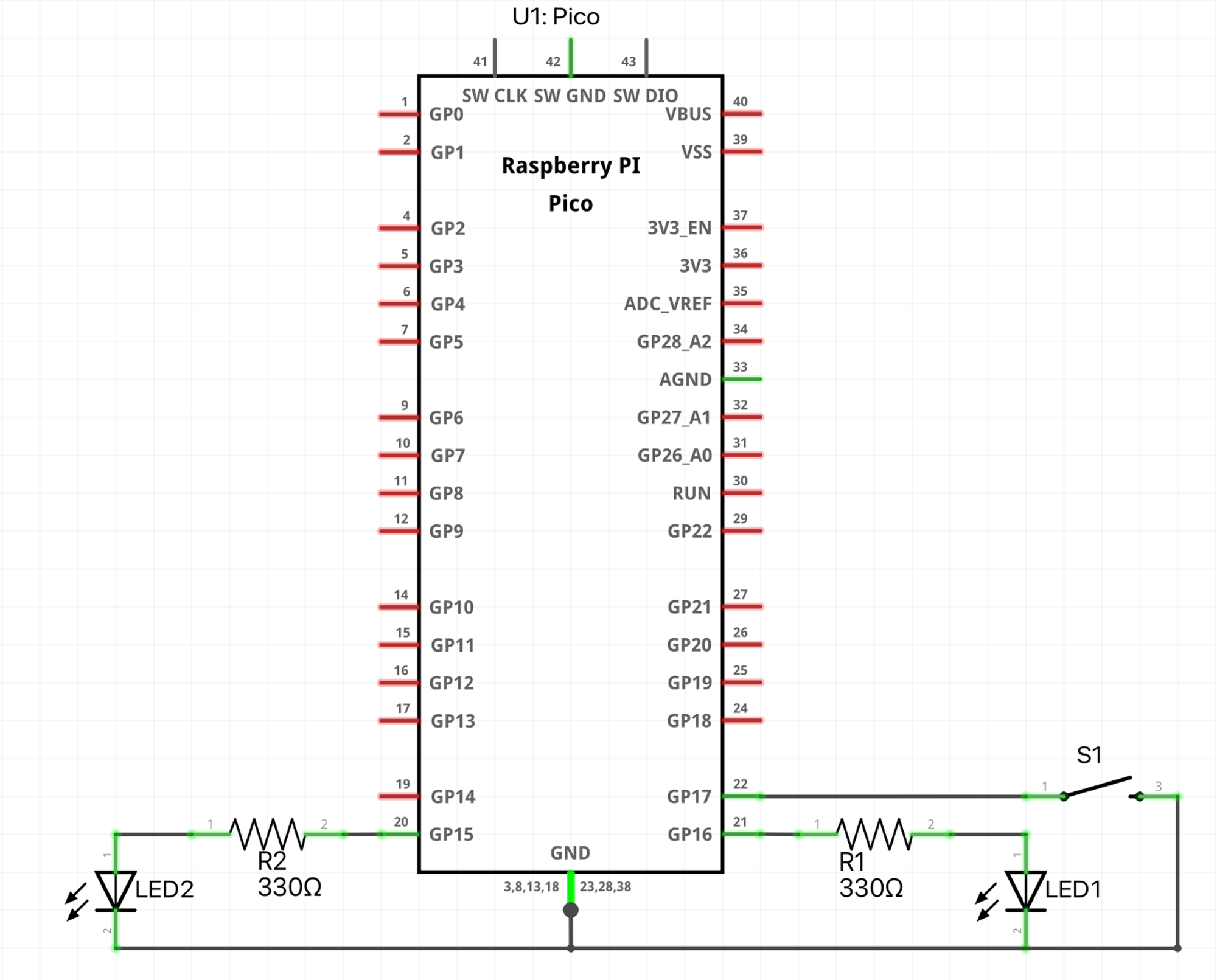
For this circuit, we connect one LED between
GPIO16 and GND through a current-limiting 330 resistor. The other LED is connected between GPIO15 and GND with another 330 resistor. The push button is connected between GPIO17 and GND.The Program
As we said above, the goal of our program is to keep an LED blinking every second while we monitor the button and flash the second LED when the button is pressed.
package main

import (
		"machine"
		"time"
)

func main() {
		// Initialize Pin 16 and configure for output.
		led := machine.GP16
		led.Configure(machine.PinConfig{
		Mode: machine.PinOutput,
		})

		// Initialize pin 15 for the 2nd LED and configure for output.
		led2 := machine.GP15
		led2.Configure(machine.PinConfig{
		    Mode: machine.PinOutput,
		})

		// Connect pushbutton to pin 17 and initialize for input with a pull-up.
		btn := machine.GP17
		btn.Configure(machine.PinConfig{
		    Mode: machine.PinInputPullup,
		})

		// Register the Interrupt Service Routine (ISR)
		btn.SetInterrupt(machine.PinFalling|machine.PinRising,
		    func(p machine.Pin) {
		        led.Set(!p.Get())
		    })

		// Keep on looping while blinking the 2nd LED
		for {
		    led2.High()
		    time.Sleep(500 * time.Millisecond)
		    led2.Low()
		    time.Sleep(500 * time.Millisecond)
		}
}
The most important part of the program is the following line in the code listing, and it involves registering an interrupt service routine (or ISR).
		btn.SetInterrupt(machine.PinFalling|machine.PinRising,
		    func(p machine.Pin) {
		        led.Set(!p.Get())
		    })
When the button is pressed, the change in state of
GPIO17 results in an interrupt being triggered. We register an interest in both the rising and falling edges of the signal via the argument machine.PinRising|machine.PinFalling. If you were only interested in the interrupt service routine being called on the rising edge or the falling edge, you would only specify one of the parameters. When the interrupt is sensed, the program invokes the callback function (commonly called the "Interrupt Service Routine" or "ISR") with one parameter, which is the pin which generated the interrupt.
In our case, the ISR is called with pin
GPIO17 (which is connected to the push button).We then read the state of the pin - which is pulled low when the button is pressed - and set the state of the LED to its inverse, i.e. high.
led.Set(!p.Get())
Remember to keep the time that the program spends in the ISR as low as possible. The idea is to be interrupted, do something quickly, and get back to executing the main program.
Ensure input pins are not left "floating"
On lines 23 - 25, we see that we configure the input pin with a mode of
machine.PinInputPullup.btn.Configure(machine.PinConfig{ Mode: machine.PinInputPullup, })
What does the mode
PinInputPullup mean?When microcontroller pins are configured as inputs, they need to be either set to a logic high or a logic low. This is normally accomplished by means of a pullup or pulldown resistor, which connects the pin either to the positive voltage source of the microcontroller or ground.
If the pin is not pulled up or down, it is possible that the pin's voltage will fluctuate depending on what is happening with other pins around it, electromagnetic interference, etc. This phenomenon is commonly called floating.
One might ask why the pin could not be connected to the positive or ground voltages without using a resistor. The reason a resistor is used is because when the pin's input changes from, say, a high to a low (as is the case with our push button), a current flows from the high voltage source to ground. Obviously, we want to minimize this current flow because an unlimited current (or a large current) can damage the microcontroller and the rest of your circuit.
These pullup or pulldown resistors are typically high in value so as to really limit the current flow in the circuit.
In the case of the Pico, the microcontroller has internal pullup and pulldown resistors, of between 50k and 80k. Using the mode
PinInputPullup activates the pullup resistor in the RP2040, thereby not requiring us to connect an external resistor.Testing the Program
Wire up the circuit as shown in the diagram above. Then, flash the program to your pico:
% tinygo flash -target=pico main.go
You should now see the LED connected to
GPIO15 blinking every second. When you press the push button, the LED connected to GPIO16 should be illuminated, and it is extinguished when you release the push button.Summary
In this tutorial we learnt:
- How to connect external LEDs and push buttons to the Raspberry Pi Pico.
- How to write a program that uses an interrupt to determine the state of the push button and use that state to take an action - in this case illuminate an LED.